Control Your 4WD Robot with an ESP32 : A Beginner's Guide
This article provides a step-by-step tutorial on how to build and control a 4WD robot using the powerful ESP32 WROOM 38-pin microcontroller1. By the end of this guide, you will have learned how to assemble the robot, wire the components correctly, and upload the code to bring your robot to life.
Getting Your Project Parts Ready
This section breaks down the essential components and tools you'll need to start building your robot.
Components and Tools Required
- Primary Components
- ESP32 WROOM 38-pin development board
- 4WD robot car chassis kit (includes chassis, 4x DC motors, wheels)
- L298N motor driver module
- Battery pack (e.g., 7.4V LiPo) or a USB power bank
- Connectivity and Tools
- Jumper wires (male-to-male and male-to-female)
- Micro-USB cable
- Screwdriver
- A computer with the Arduino IDE installed
Assembly and Wiring Instructions
Now, let's get to the hands-on part. Follow these steps carefully to assemble and wire your robot.
Circuit Wiring Steps
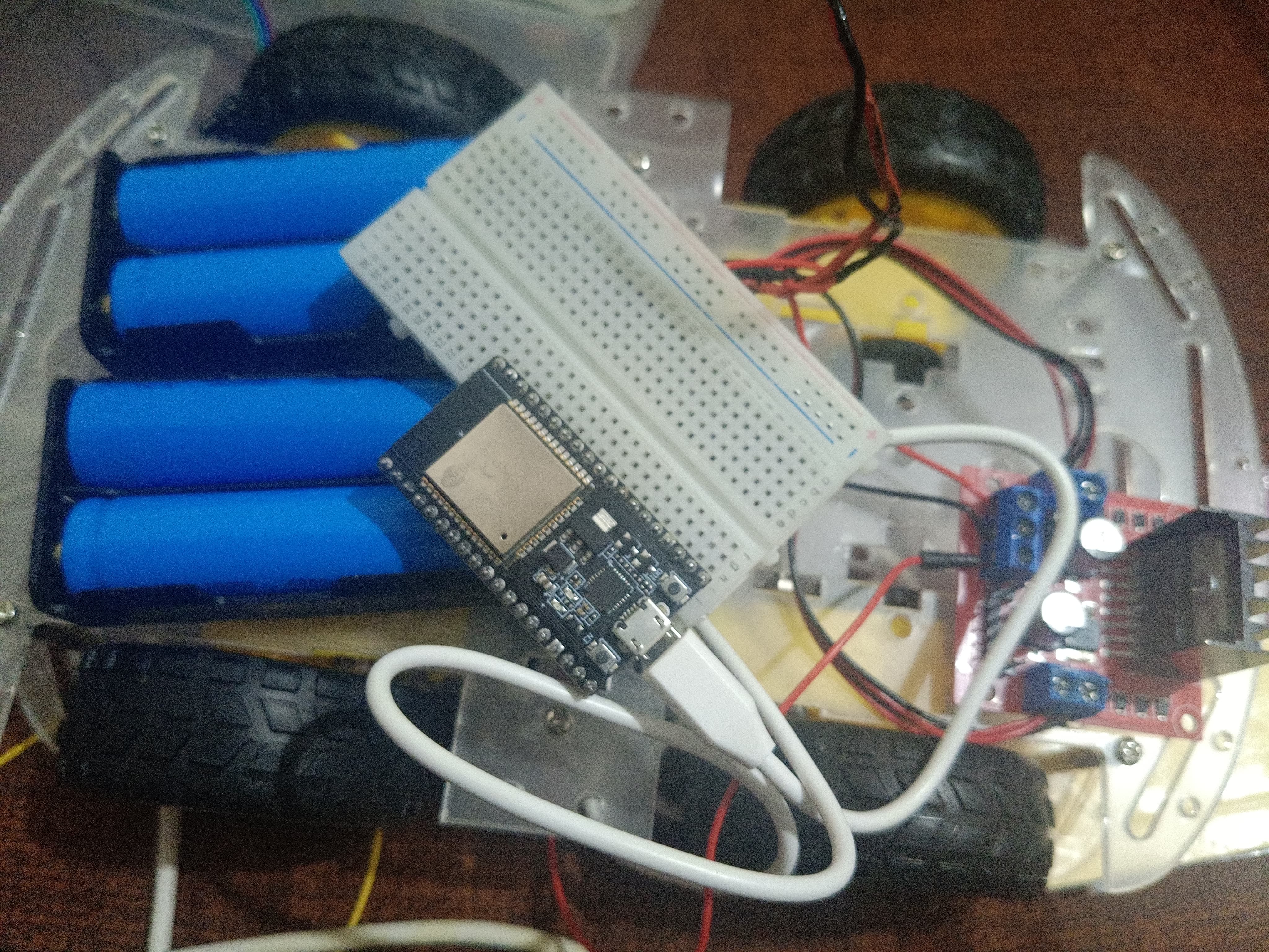
- Assemble the Chassis: Begin by constructing the 4WD robot chassis according to the manufacturer's instructions.
- Mount Electronics: Securely attach the ESP32, L298N motor driver, and battery pack onto the chassis.
- Motor and Driver Connection:
- Wire the two left motors to the
OUT1andOUT2terminals on the L298N. - Wire the two right motors to the
OUT3andOUT4terminals.
- Wire the two left motors to the
- Connect ESP32 to Motor Driver: Use jumper wires for the following connections:
- L298N
IN1→ ESP32GPIO 23 - L298N
IN2→ ESP32GPIO 22 - L298N
IN3→ ESP32GPIO 21 - L298N
IN4→ ESP32GPIO 19 - L298N
ENA→ ESP32GPIO 5(controls speed of left motors) - L298N
ENB→ ESP32GPIO 18(controls speed of right motors)
- L298N
- Power Connections
- Connect the L298N
+12Vterminal to the positive (+) terminal of your battery. - Connect the L298N
GNDterminal to the negative (-) terminal of your battery. - Important: Connect another wire from the L298N
GNDto aGNDpin on the ESP32 to create a common ground. - Power the ESP32 board via its micro-USB port.
- Connect the L298N
ESP32 Code for Robot Control
Here is the code to program your robot's movements. This should be uploaded using the Arduino IDE.
C++
// Defines the ESP32 pins connected to the L298N Motor Driver
#define ENA 5   // Enable pin for left motors (controls speed)
#define IN1 23
#define IN2 22
#define ENB 18  // Enable pin for right motors (controls speed)
#define IN3 21
#define IN4 19

void setup() {
  // Set all motor control pins to output
  pinMode(ENA, OUTPUT);
  pinMode(IN1, OUTPUT);
  pinMode(IN2, OUTPUT);
  pinMode(ENB, OUTPUT);
  pinMode(IN3, OUTPUT);
  pinMode(IN4, OUTPUT);

  // Start serial communication for debugging
  Serial.begin(115200);
  Serial.println("4WD Robot Control Initialized");
}

// Main loop to execute movement commands
void loop() {
  moveForward();
  delay(2000);
  stopRobot();
  delay(1000);
  moveBackward();
  delay(2000);
  stopRobot();
  delay(1000);
  turnLeft();
  delay(1500);
  stopRobot();
  delay(1000);
  turnRight();
  delay(1500);
  stopRobot();
  delay(1000);
}

// Function to move the robot forward
void moveForward() {
  Serial.println("Moving Forward");
  digitalWrite(IN1, HIGH);
  digitalWrite(IN2, LOW);
  digitalWrite(IN3, HIGH);
  digitalWrite(IN4, LOW);
  analogWrite(ENA, 200); // Set speed (0-255)
  analogWrite(ENB, 200);
}

// Function to move the robot backward
void moveBackward() {
  Serial.println("Moving Backward");
  digitalWrite(IN1, LOW);
  digitalWrite(IN2, HIGH);
  digitalWrite(IN3, LOW);
  digitalWrite(IN4, HIGH);
  analogWrite(ENA, 200);
  analogWrite(ENB, 200);
}

// Function to turn the robot left
void turnLeft() {
  Serial.println("Turning Left");
  digitalWrite(IN1, LOW);
  digitalWrite(IN2, HIGH); // Left motors reverse
  digitalWrite(IN3, HIGH);
  digitalWrite(IN4, LOW);  // Right motors forward
  analogWrite(ENA, 180);
  analogWrite(ENB, 180);
}

// Function to turn the robot right
void turnRight() {
  Serial.println("Turning Right");
  digitalWrite(IN1, HIGH);
  digitalWrite(IN2, LOW);  // Left motors forward
  digitalWrite(IN3, LOW);
  digitalWrite(IN4, HIGH); // Right motors reverse
  analogWrite(ENA, 180);
  analogWrite(ENB, 180);
}

// Function to stop the robot
void stopRobot() {
  Serial.println("Stopping");
  digitalWrite(IN1, LOW);
  digitalWrite(IN2, LOW);
  digitalWrite(IN3, LOW);
  digitalWrite(IN4, LOW);
}
This code defines functions for basic movements and executes them in a sequence.
Expected Outcome
Once you upload the code, your robot will begin to execute the sequence defined in the loop() function: moving forward, stopping, moving backward, and so on. The primary benefit of this project is gaining a foundational skill in robotics that can be expanded with sensors or wireless control.
Troubleshooting and Advanced Tips
- Problem: Motors aren't moving.
- Solution: Check all wiring, especially the GND connections. Ensure your battery is fully charged
- Problem: Robot moves in the wrong direction.
- Solution: Swap the two wires for the motor that is spinning incorrectly.
- Advanced Tip: You can add sensors (like ultrasonic or infrared) and modify the code to enable features like obstacle avoidance
Conclusion
In this article, we covered the main points of assembling, wiring, and programming a 4WD robot with an ESP32. You should now have the core skill of interfacing a microcontroller with motors, a fundamental concept in robotics.
Comments (0)
No comments yet. Be the first to comment!
Leave a Comment